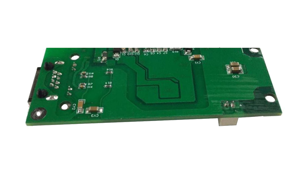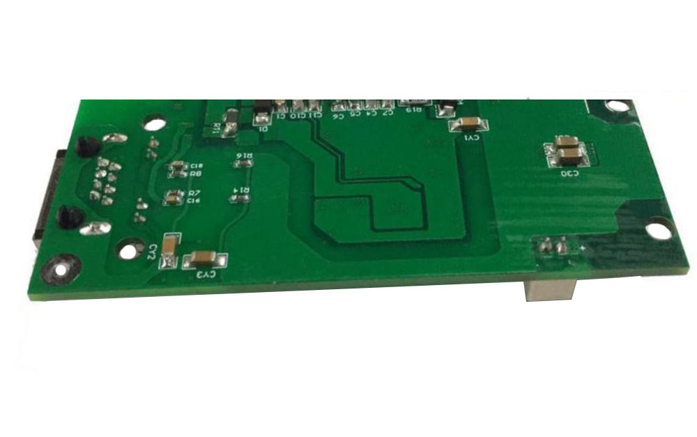
1.Product characteristics
- Compatible with IEEE802.3at standard devices.
- 42V~57V wide operating voltage range.
- Maximum output power up to 24W; Rated output: 12V/2A.
- The output ripple is less than 150 mV.
- Conversion efficiency can be as high as 88% (input 48V, output)12V@2A).
- Combined with several protection functions such as temperature control protection, current limit, high voltage internal switch, etc.
- Input/Output: isolate 1500Vdc.
- High reliability: design meets 5 million hours average failure interval
2.Scope of application
- IEEE 802.3at Compatible Devices
- Video and VoIP Phone
- PoS terminal, RFID terminal
- Fiber to Home (FTTH) Terminal
3.Describe
The POE PS30-5712T series module combines the PSE network power separation module. It can transmit data and power to non-PoE receiving devices without additional separators. The signal transmission is up to 100 meters in 10/100Mbps.
It can be freely matched with more than 85% PC modules in the market, and can also be used to power and separate the network for other devices that need PoE function.
The PS30-5712T control circuit provides the power device (PSE) required by PoE for compatibility signature and power classification, has complete protocol detection and then adds 25W power to the port.
Auto Maintain Power Characteristics (MPS) - Auto-adjust MPS for Class 1-2 or Class 3-4 PSEs - Supports ultra-low power standby mode, main adapter priority input, etc. Also has a long soft start cycle for efficient DC/DC converters to ensure IEEE802.3at start-up requirements are met.
4.Pin foot definition

Dimensions are physical (mm)
| Pin | Name | Describe |
| 1 | GND | This pin provides a negative adjustment output connected to the eight legs to provide a negative electrode for the LED. |
| 2 | LED | This pin reserves LED-R indicators for the network ports and can be set up by itself. |
| 3 | TX+ | This pin is the transmission of network TX signals. |
| 4 | TX- | This pin is the reception of network TX signals. |
| 5 | RX+ | This pin is the transmission of network RX signals. |
| 6 | RX- | This pin is the transmission of network RX signals. |
| 7 | GND | Negative DC output.This pin provides negative adjustment output |
| 8 | Vout | The DC output of the positive pole.This pin provides positive adjustment output |
5. Electrical characteristics
5.1 Absolute maximum rating parameter
| No | Parameter | Symbol | MIN | MAX | Units |
| 1 | Input DC Voltage | VCC | 42 | 57 | V |
| 2 | DC Voltage Surge 1ms | VSURGE | -0.6 | 65 | V |
| 3 | Ambient temperature | TS | -40 | 80 | ℃ |
*Exceeding the above rating may cause permanent damage to the product.Functional operations under these conditions are not recommended.
The maximum rating assumes free air flow.
5.2 Recommended working conditions
| No | Parameter | Symbol | MIN | MAX | Units |
| 1 | Input voltage | VIN | 42 | 57 | V |
| 2 | Low Voltage Lock | VLOCK | 35 | - | V |
| 3 | Working temperature | TOP | -40 | 80 | ℃ |
*Applicable only to the highest operating temperature of PS24-5712T.
5.3 output characteristic
| No | Parameter | Symbol | MIN | TYP | MAX | Units | Test Opinions |
| 1 | Standard Output Voltage | +VDC | 11.7 | 12.0 | 12.2 | V | VIN=48v |
| 2 | Output Current (VIN=48V) | PWR | - | 2.5 | 3 | A | Wide voltage input 42-57V |
| 3 | Power adjustment rate | VLINE | - | 0.1 | - | % | @50% Load |
| 4 | Load Adjustment Rate | VLOAD | - | 1 | - | % | @VIN=48V |
| 5 | Ripple Output Noise | VRN | - | 100 | 150 | mVp-p | @Maximum Load |
| 6 | Minimum Load | RLOAD | 5 | 10 | - | mA | |
| 7 | Short circuit duration | TSC | - | - | ∞ | sec | |
| 8 | Efficiency (load 80%) | EFF | - | 88 | - | % | |
| 9 | Isolation Voltage (I/O) | VISO | - | - | 1500 | VPK | |
| 10 | Temperature coefficient | TC | - | 0.02 | % | Per ℃ | |
| 11 | Dynamic response | TS | - | 60 | 100 | ms |
1: Typical number is 25 C, nominal voltage is 48V, for auxiliary design only.
2: Output ripple and noise can be reduced by an external filter, see the application instructions.
3: If operated under the specified minimum load, the module emits audible noise and may cause PSE malfunction.


